
当前位置:首页 > 产品中心
Aggregate Flow Diagram And Typical Crushing And Screening Plant Layout


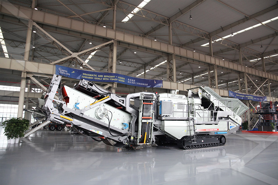
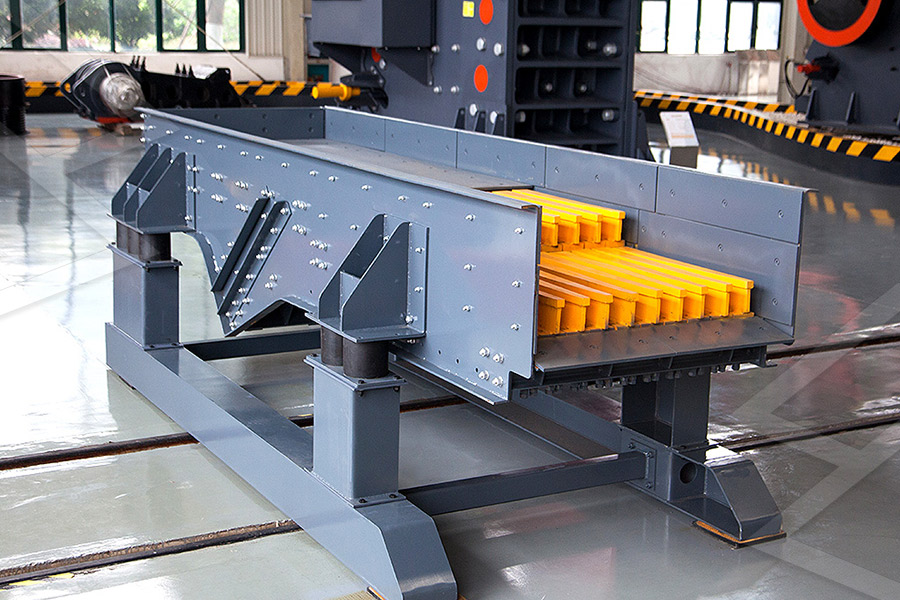
Aggregate Flow Diagram And Typical Crushing And Screening Plant Layout
2021-06-07T05:06:48+00:00
Crushing and Screening Handbook AusIMM
TABLE OF CONTENTS Chapter Subject / section name Preface Table of Contents ’s Mining and Construction Technology 1 Quarry Process + Process Integration and 2016年4月14日 A flow diagram for an aggregate processing plant is shown here This flow diagram shows a threestage gravel plant Crushing Screening Plant Design Factors 911 Figure 1 Roll crusher, left rear, threequarter view (Model 523B, C) Figure 3 Aggregate flow diagram and typical crushing and screening plant layout TM53820205101 Crushing and Screening Plant; Diesel 4 Aggregate Crushing and Screening Plant
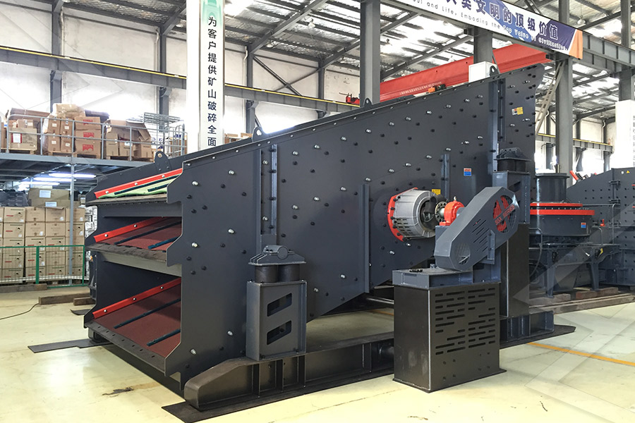
Enhanced Plant Design for Aggregate Processing AggNet
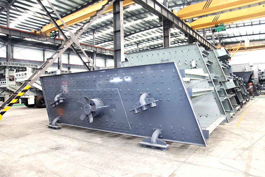
2012年10月15日 The intention of this article is to provide an overview of matters to be considered when designing a crushing and screening plant, starting with a blank sheet – when planning a plant upgrade or undergo primary crushing at the mine site before being transported to the processing plant Figure 111912 is a flow diagram for industrial sand and gravel processing The mined 11191 Sand And Gravel Processing US EPAContext 1 models presented by Bengtsson [3] are integrated into a general process plant model that can describe any type of crushing plant given that there are proper models forLayout of the final crushing stage for aggregate
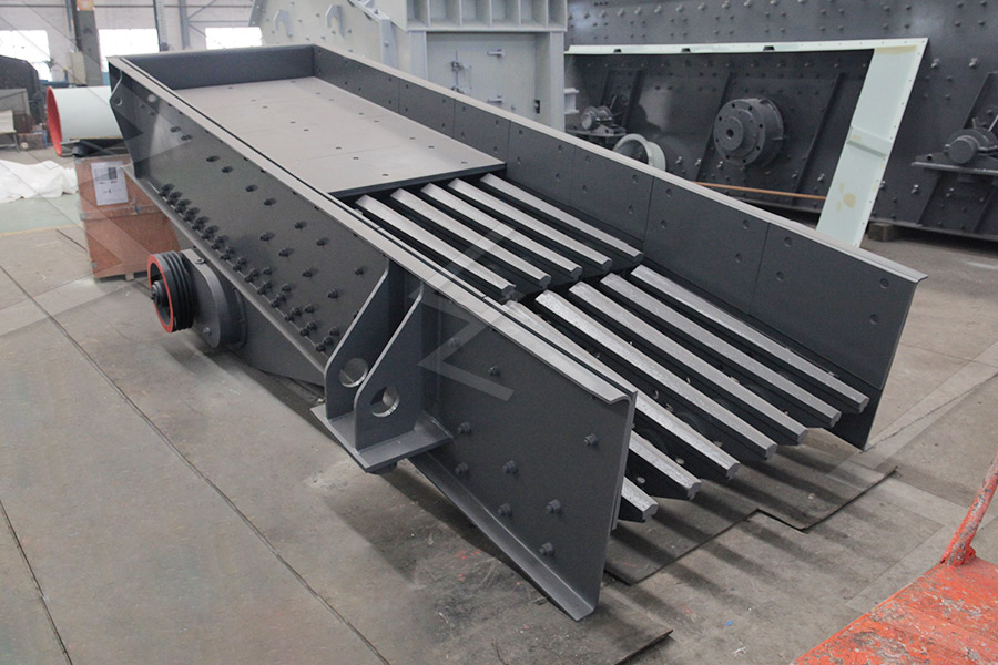
Abdulraman SO and Olaleye B IJSER
6 = Secondary Crushing; 7 = Screening and Classification; 8 = Storage/ Stockpile Figure 1: Aggregate Quarry Processes [1] Designing a typical aggregate quarry involves This paper presents a method of integrating an experimental and datadriven approach for calibration and validation for crushing plant equipment and a process model The method uses an error Layout of a fourstage crushing plant for ballast